
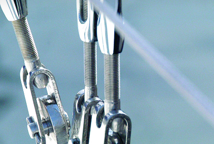
How Marine Wire Rope Assemblies Improve Reliability
A rigging failure at sea is never just an inconvenience. It can become a safety incident, a liability exposure, and a warranty claim that reaches the manufacturer long after the equipment has shipped. For marine equipment manufacturers, every load-bearing component carries that risk forward, which is why marine wire rope assemblies deserve careful engineering attention.
The difference between an assembly that reaches its intended service life and one that fails prematurely isn’t always obvious from a basic specification. Reliability depends on material selection, rope construction, termination design, corrosion control, manufacturing consistency, installation, and the conditions the assembly will actually encounter in service.
Here’s what separates a reliable marine wire rope assembly from one that’s more likely to become a field problem.
Material Selection Sets the Performance Limits
Every wire rope assembly begins with a material decision, and that choice establishes the performance limits of the system.
Type 316 stainless steel is frequently specified for marine service because its molybdenum content provides better resistance to chloride-induced pitting and crevice corrosion than Type 304. No stainless steel is completely immune, though. Warm saltwater, stagnant conditions, deposits, surface contamination, and restricted oxygen can still create aggressive corrosion conditions even in 316.
The correct material depends on the environment, expected service life, strength requirements, inspection access, cost, and the consequences of failure. Depending on the application, manufacturers may specify Type 316 stainless steel, other stainless alloys, galvanized carbon steel, or more corrosion-resistant specialty materials.
Wire construction has to match the mechanical duty, too. A 1×19 strand is relatively stiff and low-stretch, making it common in standing rigging and structural support applications. A 7×19 cable is considerably more flexible and better suited to repeated bending and movement. Construction alone doesn’t settle the question, either—fatigue, abrasion, crushing, rotation, minimum bend radius, sheave diameter, and compatibility with the selected termination all factor into the decision.
Specifying wire rope generically, without matching material and construction to actual service conditions, introduces risk before the assembly ever leaves the shop. This is the foundation of marine equipment reliability for anything that ships with standing rigging, running rigging, or load-bearing cable.
Terminations Are Critical Load-Transfer Points
Terminations are among the most highly stressed and consequential regions of a wire rope assembly. They transfer load from the rope into fittings, pins, clevises, turnbuckles, shackles, and the supporting structure, making them critical points for design, manufacturing control, and inspection.
Swaged fittings, mechanical terminals, sockets, and spliced eyes differ in static strength, fatigue performance, slip resistance, inspectability, and corrosion behavior. The termination has to be compatible with the rope’s material, construction, and diameter, as well as the fitting geometry and loading mode it will see in service.
A finished assembly should be rated based on its weakest component, not the published breaking strength of the rope alone. Termination efficiency, required design factor, peak loads, dynamic loading, expected misalignment, shock loading, and environmental degradation all have to be accounted for in the design.
For swaged assemblies, manufacturing control is essential. Incorrect dies, insufficient or excessive compression, poor alignment, damaged wire, or a failure to verify finished dimensions can all reduce termination strength and fatigue life. A controlled process should include documented tooling, calibrated equipment, dimensional inspection, material traceability, and proof or qualification testing where required.
This is where custom cable assemblies can reduce risk relative to off-the-shelf options—but “custom” isn’t evidence of performance by itself. The design, materials, manufacturing process, and final inspection still have to be verified.
Saltwater Corrosion Resistance Requires More Than Stainless Steel
Saltwater exposure creates several corrosion mechanisms: galvanic corrosion between dissimilar metals, crevice corrosion at tightly confined joints, and localized pitting where chlorides or deposits interfere with the stainless steel’s passive surface layer.
Accelerated salt-spray testing is useful for comparing materials, coatings, and manufacturing consistency, but it doesn’t reproduce every condition encountered in marine service and shouldn’t be treated as a direct prediction of field life.
Real saltwater corrosion resistance requires attention to the entire assembly, not just the alloy. Galvanic-corrosion risk should be managed through compatible material selection, electrical isolation where practical, favorable component geometry, drainage, and appropriate protective systems—and the relative exposed areas of dissimilar metals matter, since a small anodic component connected to a large cathodic component can corrode rapidly.
Termination details should minimize crevices and prevent contaminated water from collecting around the fitting, whether through a validated sealing system or reliable drainage, drying, cleaning, and inspection access. A partial or deteriorated seal can make the problem worse by trapping saltwater where it can’t evaporate or be inspected.
These details are what separate marine hardware components engineered for saltwater service from components that are simply made from stainless steel and marketed as marine-grade.
Application-Specific Engineering Multiplies Reliability
Even the right material and a properly manufactured termination may not deliver dependable service if the assembly wasn’t designed for its actual application. Engineers have to weigh maximum operating load, required design factor, static, cyclic, and shock loading, load direction and possible misalignment, bending frequency, sheave and pulley diameter, groove condition, abrasion and contact points, temperature and immersion, corrosion exposure, inspection access, and the consequences of failure.
For cables that repeatedly bend over sheaves or pulleys, the ratio between sheave diameter and rope diameter strongly affects fatigue life. A cable bending around an undersized sheave can experience accelerated wire fatigue even when the applied load stays below its rated working limit.
The connecting hardware belongs in that same engineering review. A wire rope assembly can’t compensate for an undersized pin, a poorly aligned clevis, a worn sheave, an inadequate attachment point, or a supporting structure that can’t safely carry the load.
Application-specific engineering means designing for the vessel, equipment, load path, and operating environment the assembly will actually encounter. It doesn’t eliminate the need for conservative design factors or compliance with applicable standards—it just means the design starts from the real conditions instead of a generic assumption.
Manufacturing Consistency Matters as Much as Design
A strong design can still fail in the field if production isn’t consistent. Reliable assemblies require repeatable control over material identity, rope diameter, cut length, terminal preparation, swaging dimensions, fitting alignment, and final inspection. Where the application warrants it, proof testing or destructive qualification testing helps verify that the finished assembly performs as intended.
Traceability matters just as much. Material certifications, lot identification, production records, inspection results, and test documentation give manufacturers a way to investigate field issues and confirm that an assembly was built to the approved specification—controls that carry real weight in safety-critical or warranty-sensitive applications.
Wire Rope Maintenance Extends What Good Engineering Starts
No wire rope assembly should be treated as maintenance-free. Regular inspection should look for broken wires; pitting, corrosion, or rust staining; abrasion or flattening; kinks, birdcaging, or other distortion; diameter reduction; cracked, bent, or loose terminals; terminal movement or cable pullout; wear at sheaves, fairleads, and other contact points; damaged jackets, coatings, or seals; and unauthorized modifications or repairs.
Inspection frequency should be based on operating severity, load cycles, environmental exposure, accessibility, and the consequences of failure, with retirement criteria following the assembly manufacturer’s instructions and any applicable industry or regulatory requirements.
Manufacturers can improve long-term reliability by building inspection intervals, replacement guidance, wear indicators, and clear retirement criteria into their product documentation. That gives end users a practical way to catch degradation before it becomes a failure.
Building Reliability In From the Start
Reliable marine wire rope assemblies aren’t the result of a single material or manufacturing decision. They come from matching material and rope construction to the environment, selecting a termination compatible with the load and duty cycle, controlling the manufacturing process, accounting for bending and corrosion, rating the complete load path, and providing clear inspection and retirement guidance.
For manufacturers whose equipment depends on cable and rigging systems, that level of engineering attention protects personnel, reduces field failures, supports warranty decisions, and preserves the reputation of the finished product long after it ships.
Explore Hayn.com to learn how our custom wire rope assemblies are engineered around the application, operating environment, and performance requirements of each project.